Lubrication System Design
The purpose of this page is to assist you with some practical tips to help with designing a lubrication system for your needs.
Lubrication System Design Step No. 1
Before designing a Bijur Single Line Resistance lubrication system, it is first important to be informed about the different types of systems:
Manual
lubrication systems operate by the activation of spring-actuated piston pumps.
- Automatic lubrication systems have various actuation methods:
- Rotary-drive from machinery or equipment (cyclic)
- Self-contained motor driven with built-in gear reduction (cyclic)
- Timer actuated pneumatic pumps (cyclic)
- Timer, controller or PLS actuated gear pumps
- Automatic Continuous Systems normally operate with rotary-driven gear pumps.
Lubrication System Design Step No. 2
Understand the importance of selecting the proper size resistance fittings for each point in the lubrication system.
Lubrication System Design Step No. 3
Draw a schematic diagram of the equipment and indicate each point requiring lubrication. Retain the diagram for use during installation to insure no points are overlooked.
Lubrication System Design Step No. 4
Use this checklist to ensure proper consideration is given to each step of the lubrication system design
- Locate and identify friction points or types of bearings on the equipment. Refer to the machine manual to determine the accurate size and configuration of each point or estimate bearing size if necessary. Complete the system schematic.
- Calculate the oil requirement for each bearing point and record the amount next to each point. It is important that each point is calculated separately.
- Calculate total lubrication system oil requirements by adding the individual point requirements. Record on the schematic.
|
Bearing Type
|
Calculate Oil Requirement
(cc/hour) by multiplying
|
|
anti-friction bearing
|
0.10 x bearing shaft diameter
(in.) x number of rows (balls, rollers, etc.
|
|
plain bearings and drive screws
|
0.15 x bearing shaft diameter
(in.) x bearing length (in.)
|
|
gears
|
0.30 x fear pitch diameter (in.
) x face width (in.)
|
|
cams
|
0.08 x surface area (sq. in.)
|
|
chains
|
0.05 x length (in.) x width (in.)
|
|
slides and way flat
|
0.04 x [length of moving member
(in.) + travel (in.)] x width (in.)
|
|
cylindrical
|
0.15 x diameter (in.) x [length
of moving member (in.) + travel (in.)
|
|
ball bearing
|
0.03 x travel of moving member
(in.) x number of rows
|
- Select an appropriate lubricator capable of delivering sufficient quantities of oil to the entire system.
- Specify resistance fittings for each point in the system
- Refer to table to select the proper flow rate for the system type you are designing (continuous loss, cyclic or continuous re-circulating).
- Assign the sizes of the resistance fittings starting with the mid-range point that requires the least amount of oil. Continue with all other resistance fittings in the system based on their relative size (discharge volume) to other points. Points requiring similar amounts of oil will be supplied from resistance fittings of similar size.
- Determine total system flow value (ɸT). To do this, add the flow value (ɸ) of each resistance fitting. After that, multiply the flow value of each fitting to the number of points in that group (see figure).
- For cyclic lubrication systems: Check selection of resistance fittings with total system requirement. If total (ɸ) exceeds pump rating (refer to table) select a larger pump or smaller resistance fitting.
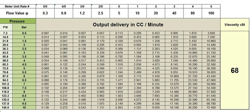
- For continuous lubrication systems: Determine and specify fittings, junctions, connectors and distribution tubing. Calculate system operating pressure according to this formula: P = FV/ ɸ, where: P=pressure at operating temperature; F=total required (or calculated) flow in cubic centimeters per minute (cc/min); V=viscosity of oil in system at operating temperature measured in Saybold Seconds Universal (SSU); ɸ=total flow (ɸT) of system.
Lubricating System Design Step No. 5
Prove the system by comparing the calculated oil discharge with the actual discharge from the lubricator you selected. To do this, use this formula:
Divide device flow value by total system flow value, and then multiply by pump discharge volume.
The result is the actual metered discharge for that point (see figure 3-2.)
|
Table 3.2 Recommended Flow Rates for Various System Types
|
|
Flow Rate
|
Flow Value
|
CONTINUOUS “LOSS”
|
|
5/0
|
0.3
|
|
|
4/0
|
0.6
|
|
|
3/0
|
1.2
|
CYCLIC “LOSS”
|
|
00
|
2.5
|
|
|
0
|
5.0
|
|
|
1
|
10.0
|
CONTINUOUS
“RE-CIRCULATING”
|
|
2
|
20.0
|
|
|
3
|
40.0
|
|
|
4
|
80.0
|
|
|
5
|
160.0
|
|
To prove that the cyclic system is adequate, compare the flow characteristic of each meter unit to the flow value of the overall system. Multiply this ratio to the total pump shot size and you will calculate metered discharge amount per point.
Lubricating System Design Step No. 6
Lubricating System Design Step No. 7
|
